Angles. Projections. Polyhedral angles
straight lines, two crossing straight lines. Perpendicular to a plane.
Projections. Projection of a point and a segment to a plane. Dihedral
angle. Linear angle of a dihedral angle. Angle between two planes.
Perpendicular planes. Angle between two perpendicular planes.
Angle between two parallel planes. Polyhedral angle. Plane angles.
Trihedral angle as a minimal polyhedral angle. Parallel sections of
a polyhedral angle.
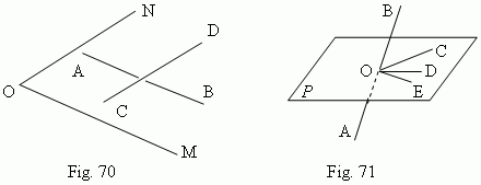
Angles. An angle between two intersecting straight lines is measured as well as in a planimetry ( because it is possible to draw a plane through these lines ). An angle between two parallel straight lines is accepted equal to 0 or 180°. An angle between two crossing straight lines AB and CD ( Fig.70 ) is determined as follows: through any point O the rays OM and ON are drawn so, that OM || AB and ON || CD. Then an angle between AB and CD is accepted equal to an angle NOM. In other words, the straight lines AB and CD are transferred to a new position parallel to themselves until their intersection. Particularly, the point O can be taken in one of the lines AB or CD, which is immovable in this case.

The straight line AB, intersecting the plane P in the point O ( Fig.71 ), forms different angles ( the angles BOC, BOD, BOE ) with the different straight lines OC, OD, OE, drawn in the plane P through the point O. If the line AB is perpendicular to the two of these straight lines ( for instance, OC and OE ), then it is perpendicular to all the straight lines, drawn in this plane through the point O. In this case the straight line AB is called perpendicular to the plane P, and the plane P – perpendicular to the straight line AB.
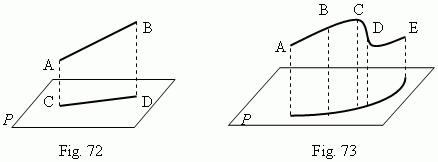
Projections. A projection of the point A to the plane P is called a base C of the perpendicular AC, drawn from the point A to the plane P. A projection of the segment AB to the plane P is the segment CD, ends of which are projections of the points A and B ( Fig.72 ). It is possible to project not only a straight line, but any curve ABCDE ( Fig. 73 ) to a plane.

Lengths l of the projection CD and a of the segment AB ( Fig.72 ) are tied by the relation:

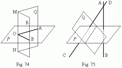
Dihedral angle. A figure, formed by two half-planes Q and R, going through the same straight line MN ( Fig.74 ), is called a dihedral angle . The straight line MN is called an edge of a dihedral angle; half-planes Q and R – its faces . The plane P, perpendicular to the edge MN, gives the angle AOB in its intersection with the half-planes Q and R. The angle AOB is called a linear angle of a dihedral angle. A linear angle is a measure of its dihedral angle.

Angles between planes . Two planes are called perpendicular planes , if they form a right angle. An angle between two parallel planes is accepted equal to zero. In general case an angle between two planes P and Q ( Fig.75 ) can be measured by an angle, formed by the straight lines AB and CD, which are perpendicular to the planes P and Q correspondingly.
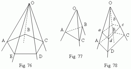
Polyhedral angle. If to draw through the point O ( Fig.76 ) a set of planes AOB, BOC, COD etc., which are consequently intersected one with another along the straight lines OB, OC, OD etc. ( the last of them EOA intersects the first AOB along the straight line OA ), then we receive a figure, called a polyhedral angle. The point O is called a vertex of a polyhedral angle. Planes, forming the polyhedral angle (AOB, BOC, COD, …, EOA), are called its faces ; straight lines, along which the consequent faces intersect ( OA, OB, OC, … , OE ) are called edges of a polyhedral angle. Angles AOB, BOC, COD, … , EOA are called its plane angles . The minimal number of faces of a polyhedral angle is 3 ( the trihedral angle , Fig.77 ).

Parallel planes cut off the proportional segments ( OA:O a = OB:O b = OC:O c = …) on edges of a polyhedral angle ( Fig.78 ) and form the similar polygons ( ABCD and abcd ).